Client Statement
Ans- yes.
Conceptual Design
We did 3 conceptual design, which is carried out by 3 different groups. In which 2 are presented in this blog.
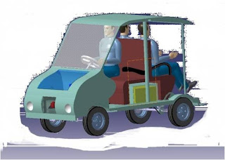
This concept presented by Karthik patil and group. in which the concept was generated according to the sitting position o the passengers. The sitting position is as shown in the figure. where the battery box come under the passenger seats ans the rear passenger sit exactly on the rear axle. and the engine was mounted on the front side of the vehicle.
 The concept was generated by Vinay Patil , Paven D and group in this concept the front passenger sit normally, but the rear passengers sit facing opposite to each other, in this concept the rear seats can be slide out side to make easy for the passenger get in. But, this concept not taken considerations of engine mounting.


After the notching or making cutting the chassis long member as shown in the engineering Drawings. and joining the it in the desired manner. with good welding process.


According to above drawing the final fabricated assembly of chassis frames.
 The assembly drawing showing the information about the position of seat, front wheels, rear wheels front suspension, rear suspension, steering mounting locations. etc is shown in this drawing. according to which other fabrications are carried out.


We participated in the JED-i computation held in the IISc Bangalore. 10 jun 2011


“Design a campus vehicle”
The client has given a list of objectives which are as follows:
- To travel within the campus for the disabled and help the older people visiting the campus.
- It must also act as shuttle between the college campus and the hostels (boys & girls) for the needy students.
- It must be simple and well furnished.
- It must accommodate 3+1 persons with small luggage space.
- A technological approach from BVB students.
Clarifying Objectives:
- How much should it cost?
Ans- around 2 lacs
- Will the differently abled people climb into the vehicle on their own or will a special device be fitted into the vehicle to help them?
Ans- not necessary , more friendly handle, bar, no need of automotive devices.
- Should the student teams use the resources (Workshop/Manufacturing) available in the college only?
Ans- not for experimental piece in the department.
- Does 3+1 indicates 3 passengers and 1 driver? Will there be a dedicated driver to the vehicle?
Ans- 3+1 necessary.
- What is the maximum amount the client is willing to spend?
Ans around 2 lacs
- To use a technological approach, the student teams have to work on battery powered motors, solar panels, i.c. engines. Does hybrid include battery powered motors, solar panels and i.c engines?
Ans – combination of gasoline and engine, and keeping in mind of future design
- What should be the typical life span of the vehicle? Should it be maintenance free?
Ans- life for 4 yrs, and yes maintaince free.
- Whether the vehicle should have the doors or not?
Ans- no doors.
- Will the vehicle be used for any other purpose than already mentioned?
Ans-only for campus travel, guest, disable person.
- What should be the maximum speed of the vehicle?
Ans- 25-30 km/h
- Will it be used at night also?
Ans- yes in nights
- Will it be used under rainy conditions? Whether it will be used for all weathers?
Ans- not necessarily but design should kept in mind.( rating - 2 out of 10
- Will it move only on tarred and concrete surfaces?
Ans- yes it should
- Should we use green technology wherever applicable?
Ans- yes
- Can the student teams use some technology more for demonstrative purpose rather than usefulness?
Ans- yes.
Conceptual Design
We did 3 conceptual design, which is carried out by 3 different groups. In which 2 are presented in this blog.
This concept presented by Karthik patil and group. in which the concept was generated according to the sitting position o the passengers. The sitting position is as shown in the figure. where the battery box come under the passenger seats ans the rear passenger sit exactly on the rear axle. and the engine was mounted on the front side of the vehicle.


The Chassis long member Drawing given for the bending operation using 3mm sheet metal in the Kranthi industries Hubli.

The initial bending process of chassis long member and cross member is carrying out in Kranthi industry Hubli. chassis team member Mallikarjun, and Team leader Pavan giving information about the requirements.

The notching operation carrying out on the chassis, this operation is done to get the required shape of the long member. which can be seen in next slides.

After the notching or making cutting the chassis long member as shown in the engineering Drawings. and joining the it in the desired manner. with good welding process.

Chassis Long members are prepared. in the college work shop, our assistant instructor Mr. Allamavaver carrying the welding process.
The Drawing given to carry out Fabrication using welding process on chassis. which include joining of long member and cross member of the chassis and the suspension mounting point details.

According to above drawing the final fabricated assembly of chassis frames.


According to the above details given in the Drawings, the fabrication of engine mounting, front suspension, rear suspensions, front wheels, rear wheels, battery box etc.

The details drawings of the body parts. and and development of the materials required body part is given in the drawing.


Fabrication of body completed according to drawings given above.


